Hammer Spare Parts
- Home
- Hammer Spare Parts
Anvil Block

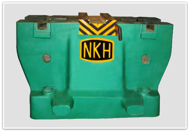
Made of grey cast iron, weighing approx. 20 times the nominal capacity of the ram, it is machined on both top & bottom faces to hold the die holder firmly and maintain the position of the columns. The die holder fixed in the anvil block is forging from high-grade alloy steel all over hardened and it is positioned properly with help of an alloy steel tapered wedge.
Columns, Slides and Tup
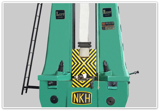
Cast steel columns are positioned by a large spigot on the underside of each foot which fits into a machined recess in the anvil block. The columns are locked with the help of tapered wedges of alloy steel to ensure firm alignment of columns. The clearance between the tup and guideways attached to columns is maintained with the help of a tapered wedge which brings the columns inward and the drawback bolt provided pushes the columns outwards. A synthetic rubber mat is provided on an anvil block on which the columns rest. It dampens the induced shock vibrations which increase the life of the tup and also ensure smooth working of the machine for a longer period.

Head Assembly & Lifting Mechanism

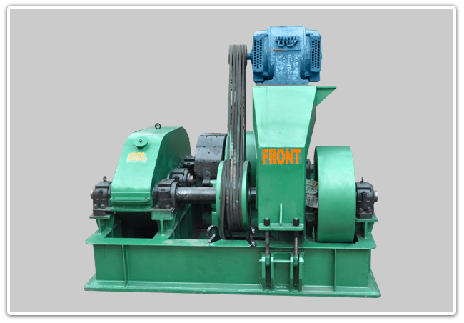
Heavy-duty head assembly fabricated from rolled steel sections is mounted on top of the columns. The drive is through v-belts from high torque A.C. Electric motor via flywheel and reduction gears to the lifter-shaft. A friction lifting system is fitted to the lifter shaft which runs on spherical roller bearings (SRB) and one central phosphorus bronze bearing bush which also serves as support to the lifter shaft. The friction lifter consists of a constantly rotating drum and breaks lined steel band. This band is anchored at one end to stud in lifter drum and the other end is carried by camshaft running through lifter drum which actuated by a lever. The lever is operated with the help of a pulling cord tied to the lever at one end goes to the operating point by passing through capstan bush attached to the lifter shaft. When the cord is pulling it tightens onto the rotating capstan bush which operates the lever resulting in tightening of the brake around the brake drum with the help of the camshaft. At this stage lifter drum is rotated and to tup is lifted with the help of the nylon belt provided. On the release of the cord, the spring-loaded arrangement helps free fall of tup by disengaging the friction band immediately from the friction drum. The spring-loaded buffer work as a stopper for lifting the drum in its rest position. Positive water cooling arrangement is provided to the friction drum to prevent excessive heating.

